Friday, May 26, 2017
How To Design A Fire Hydrant System
How To Design A Fire Hydrant System
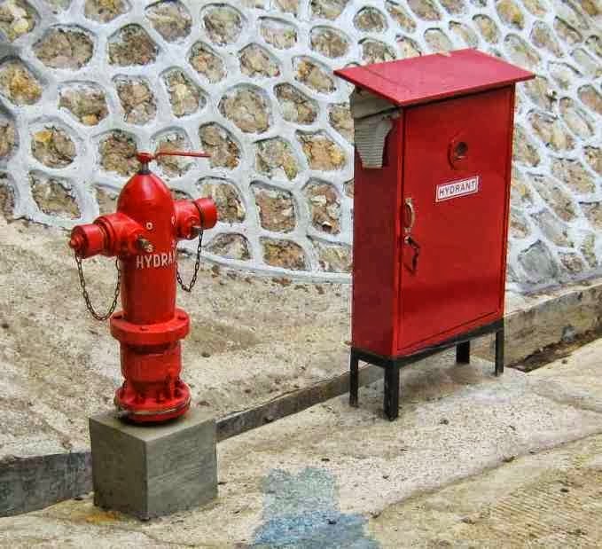
Hydrant Pillar & Outdoor Hidrant Box
Before we design we must first determine the needs of the unit fire hydrant in the area that we will design. in this case we determine the location of the hydrant with one another is based on the hydrant hose range is 30 m.
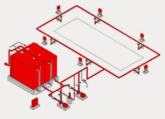
Example :
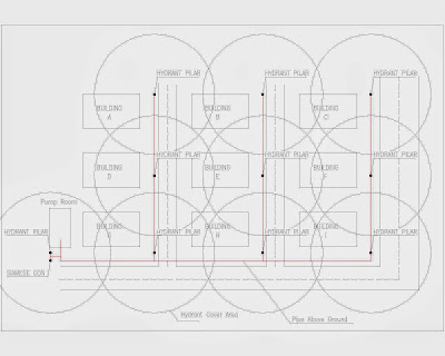
Note :
Hydrant Pillar 10 Units
Cover area 45 m
Flow rate 80 gpm
working pressure 10 kg/cm2
2. Pump capacity
80 gpm x 10 = 800 gpm
Area fire 30% of the buildings on the layout, the figure of 30% is very useful to determine the capacity of the pump
800 gpm x 30% = 240 gpm
After a known requirement is 240 GPM pump, now we have to look at the table to determine the pump.
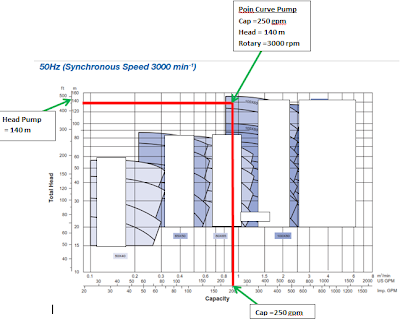 |
| Pump Curve |
Seen from the table above, we get a kind of pump that is:
Capacity = 250 gpm
Head = 140 Meters
Rotary = 3000 rpm
2. Calculate Pipe For Fire Fighting
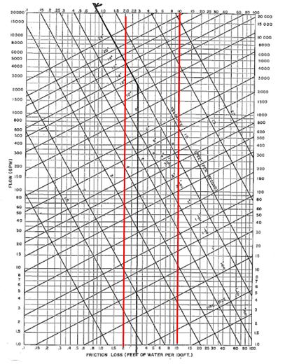
For more table Click Here
To calculate the diameter that will be installed, we have to calculate the start of the end of the water demand.
if the needs of each fire fighting is 80 gpm. Based on the table above, then we will get the size of the pipe with a diameter of 2 1/2 Inch.
Or you can use a calculator pipe following :
if the needs of each fire fighting is 80 gpm. Based on the table above, then we will get the size of the pipe with a diameter of 2 1/2 Inch.
Or you can use a calculator pipe following :
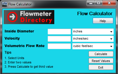
Download
Now weve got the size of the end of the pipe that will be installed.
after that we add the required amount of water based on the amount of fire fighting to determine the size of the next pipe, and continue to add up until the end of the pump.
Note:
Keep in mind!!!!! ... Operator may not use the fire fighting them simultaneously.
for that you should be able to assume how many meters each operator will be using, so that you can determine the proper pipe size requirements.
Suppose there are 15 in the area of ??fire fighting, probably in use only 5 or 6 that simultaneously. so the size of the pipe is calculated up to the end of the pump may be sized for 5 to 6 fire fighting.
Calculation of pipe are finished,,
How??
Easy right??
3.Pump Room Instalation

Fire Pump Package
a. Diesel Fire Pump
function:
As a backup fire pump if electrical power is not available anymore for extinguishing operation.
Powered by Diesel Engine
Start operation automatically based pressure sensors (pressure switch)
Stop operation manually based pressure sensors (pressure switch) AND the Stop button.
b. Electric Fire Pump
function:
As the main fire pump.
If the sprinkler breaks or Hydrant Pillar opened for extinguishing the fire, the electric pump will operate automatically.
operation:
Driven by electric motor
Start operation automatically based pressure sensors (pressure switch)
Stop operation manually based pressure sensors (pressure switch) AND stop button.
c. Jockey Fire Pump
function:
Keeping the pressure in the pipeline remains in standby
If there is a small leak in the pipeline, it will operate Jockey Pump (automatically) to restore pressure in the network.
operation:
Driven by electric motor
Start & Stop operation automatically based pressure sensors (pressure switch)
d. Hydrant Box Detail

Hydrant Box Detail
Go to link download